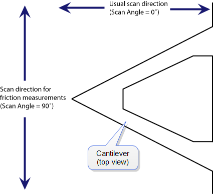
The cantilever is most susceptible to frictional effects when the scan direction runs perpendicular to the major axis of the cantilever. The Scan Angle parameter in the Scan panel must be set to 90° or 270° to produce this scan direction.
The Contact AFM mode setpoint voltage will slightly adjust the gain of the lateral force signal. By increasing the setpoint, the contact force applied will increase, and so will the frictional or torsional forces in an approximately linear fashion. If the frictional effects are too large or too small, change the cantilever, but if the value is near the dynamic range desired, adjustment of the contact force will produce modest changes in the lateral force or frictional signal.
The analog-to-digital converter on the auxiliary input channel used for LFM data has a maximum input range of ±10 V. This, and the anticipated interaction between tip and sample define the selection of the cantilever to be used for the measurement.
A 200 µm cantilever with wide legs provides a good starting point for frictional measurements. It is flexible enough to provide reasonable signal levels on samples with moderate friction. If the signal exceeds +10.00 V with a 200 µm wide-legged cantilever, one of the stiffer 100 µm cantilevers should be used. If the signal level is too small, the narrow-legged 200 µm cantilever will provide a larger signal.
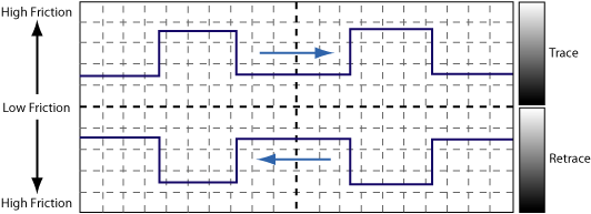
LFM data is typically monitored in the trace direction with the scan angle set to 90 degrees. The data then follows a convention where lighter colors mean higher friction and darker colors mean less friction. The sign of the color is inverted if Retrace is monitored:
It is possible to enhance the magnitude of the LFM data by subtracting the trace from the retrace. This is done by collecting three data channels with one scan.
|
|
|
|
|
|
|
|
|
|
Information about the Subtract Image function can be found the NanoScope 8.15 Software: User Guide. |
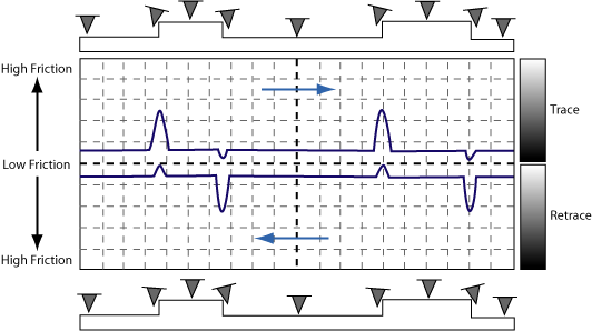
LFM is subject to height artifacts due to coupling with surface topography. Delay in the feedback loop causes the tip to momentarily twist as it climbs up an edge. This will be visible in the friction data if it is severe enough.
To distinguish real friction data from height artifacts, remember that friction causes the cantilever to twist in the opposite direction as it travels. Actual LFM information will always show up as a mirror image in the trace and retrace directions in the scope display. Height artifacts will be the same direction in the scope display:
| www.bruker.com | Bruker Corporation |
| www.brukerafmprobes.com | 112 Robin Hill Rd. |
| nanoscaleworld.bruker-axs.com/nanoscaleworld/ | Santa Barbara, CA 93117 |
| Customer Support: (800) 873-9750 | |
| Copyright 2010, 2011. All Rights Reserved. |
 Related Topics